DO NOT SCRAP IT! MODERATED NATIONAL EXCHANGE NEWSGROUP FOR SALVAGERS > Iowa
> Tektronix signal scout RFM151 coax catv rf meter
Tektronix signal scout RFM151 coax catv rf meter
Tektronix signal scout RFM151 coax catv rf meter
CATV RF Measurement Field Tool
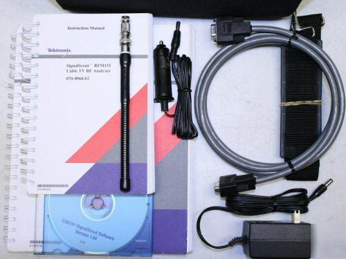
Included Accessories Listed at the Bottom.
Be sure to add us to your Favorites list!.
Warranty: 30 Day Exchange Warranty
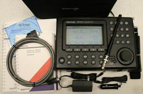
The Tektronix SignalScout RFM151 is a high-performance RF measurement field tool tailored for analog/digital Cable TV networks. It is designed to meet the demanding requirements of cable television technicians performing troubleshooting and maintenance operations anywhere in the network. The RFM151 provides all of the basic signal level
measurement capabilities, and it also adds new spectrum analysis, ingress, and digital channel RF measurement capabilities not available in comparable products!
* Digital Channel RF Measurement Suite Includes Average Power Level Plus Noise/Distortion Measurement
* Exclusive Ingress Monitor Mode Records Ingress Violations of up to 32 User-defined Frequency and Level Windows
* Enhanced Spectrum Mode Increases Ability to Capture Lowlevel and Bursty Signals
* AM and FM Demodulators with Speaker Helps Identify Ingress Sources
* User-changeable Battery Pack with Optional External Charger for Uninterrupted Use
* CSS151 Control and Analysis Software Includes Ingress/Spectrum Analysis Capability and Report Generation
The RFM151’s stepped integration method efficiently and accurately delivers the true average power of QAM, QPR, QPSK, or VSB digital channels (see Figure 1). Unlike single-point measure and calculate methods, the stepped integration technique takes into account signal abnormalities such as un-flatness.
The Peak Analog-to-Digital Average Power Level Difference measurement makes short work of verifying power loading in mixed analog and digital systems. Use it to set digital modulator levels referenced to the analog carriers.
With analog signals, carrier-to-noise ratios are important to picture quality. A similar measurement for digital signals is the Desired-to- Undesired Signal Ratio. This is an in-channel (out of service) average power-to-noise measurement that includes noise, as well as distortion signals, such as ingress and analog system-generated CSO and CTB.
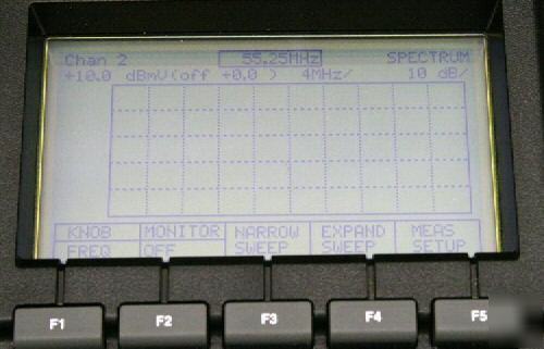
The RFM151’s Spectrum Mode is an easy-to-use spectrum analysis tool that allows technicians to troubleshoot most problems before calling for more advanced equipment. Spectrum Mode Features include:
Combination AM/FM demodulators with amplifier and speaker, are available both in Meter Mode and Spectrum Mode. These detectors help the technician identify both wanted signals, such as aural carriers, and unwanted signals, such as a two-way radio transmission, and other ingress.
The General Purpose Spectrum Mode offers a choice of no markers, dual frequency-amplitude markers with D readout, or noise markers (in dB/Hz) with selectable normalized bandwidth. Other features of spectrum mode include: Window Sweep which reduces the amount of swept display, increasing the display update rate to show rapidly changing signals; Max Hold, to show only the highest value of the displayed spectrum; Selectable Peak or Average detection modes, and a preamp for making ow-level readings.
The RFM151 is the technician’s best friend when it comes to troubleshooting ingress problems. Exclusive circuitry minimizes forward-path signals overloading the RFM151’s input when measuring return-path traffic. This means that low-level ingress measurements can be taken in common path locations – such as a tap or seizure screw. Add to this the quick scan rate of Window Sweep, max hold, peak detect, demodulation, field strength, and preamp controls and the RFM151 is able to measure return-path bursty signals and low-level ingress down to –65 dBmV (–5dBμV) to help locate the source (see Figure 2).
Another unique RFM151 feature is the Ingress Monitor Mode which allows up to 32 frequency windows to be defined within the displayed spectrum, each with its own level threshold (see Figure 3). When a signal violates the threshold, the instrument either stops and shows the display, stores the violation in memory, or continues. Violations can be stored as frequency/amplitude/time data, or complete spectrum displays with time stamps. Sweep delays can be set from 2 to 60 minutes in one-minute intervals allowing unattended monitoring.
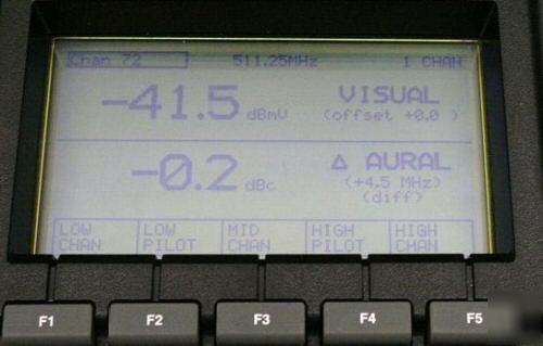
The SignalScout provides five different level displays: Single Channel, 5-channel, Pilots, All Channels, and Meter. These display modes can show either analog or digital channel information.
The 5-channel display mode provides both a numerical reading and a bargraph display. This is great for doing system-at-a-glance measurements and looking at tilt. The Pilots display mode shows both bargraph and numeric displays of any two frequencies used for setting the AGC in the plant.
The RFM151 also performs the following measurements: Carrier-to-Noise, Hum, FM Deviation, and Field Strength. Carrier-to-Noise can be configured for either In-Service (using the guard band) or Out-of-Service (with a user-settable frequency offset). Both measurements are normalized to the proper bandwidth for the system (4MHz for NTSC and 5MHz for PAL).
The Relative Field Strength mode allows the user to select a frequency between 5 and 1080MHz and use an optional antenna to locate the signal of interest. Field Strength Mode is useful for finding leaks in the cable plant and locating the sources (see Figure 4).
The RFM151 works on any world television standard and all common transmission standards. It automatically measures the average power of a NICAM sound carrier. Just enter the correct frequency into the second aural carrier slot and the RFM151 does the rest.
Customized Settings – Time-Saving Measurement Sequences
The RFM151 and CSS151 Software form a powerful tool tailored to an individual cable system. By creating automatic test sequences using the CSS151 software, test time and errors are reduced. Tests can be setup to run at fixed time intervals using the interval timer in the RFM151, or under technician control. These sequences can be used for the FCC required tests including the 24-Hour test, or just for routine maintenance.
Data in the worksheet can be printed directly, or processed into concise reports for hard copy files. Reports include a Status Report that shows how well the system is performing with regard to level differences between adjacent channels and minimum and maximum level differences. Another report shows the visual carrier level and visual-to-aural carrier difference over four six-hour time periods for monitoring system performance over time and temperature. Both reports can be printed with up to six lines of header text for displaying additional information.
Input Impedance – 75 W (nominal).
Connector Type – Male type F with precision female-to-female F
Accuracy – ±5 kHz or ±10–5 of tuned frequency,
ANALOG AND DIGITAL LEVEL MEASUREMENTS
Sensitivity – –35 to 60 dBmV (+25 to +120 dBμV).
DIGITAL TO ANALOG CARRIER DIFFERENCE
Analog Channel Select Mode – Automatic or user selectable.
Measurement Location – User selectable.
Range – Up to 51 dB with carrier amplitude >5 dBmV,
Measurement Location – Guard band
(»1.25 MHz below the visual carrier).
Range – Up to 47 dB with carrier amplitude >0 dBmV.
Measurement Location – In channel (Out of Service).
Fundamental Frequency – 50/60 Hz,
Accuracy – ±10% of peak deviation or
General Purpose (Dual/Noise/No markers).
Demod (AM, FM detectors, speaker).
(up to 32 user-defined thresholds within a displayed spectrum).
Frequency Range: 5 to 1080 MHz.
Span/Division: 4 MHz, 2 MHz, 1 MHz, 400 kHz, 200kHz.
Sensitivity: –60 dBmV (–65 dBmV typical).
Detection Mode: Peak or Average.
Vertical Scales: 2, 5, 10, 15 dB/Div.
Other Controls: Preamp, Max Hold.
Operating: 0 to +50° C (+32 to +122° F).
Operating: 5 to 95% from 0 to +50° C.
Operating: Up to 15,000 ft. (4,550 m).
Non-operating: Up to 40,000 ft. (12,192 m).
DC Input Range – +10 to +15 VDC.
Power Requirement – 10 W maximum.
Battery Type – User replaceable.
* Tektronix SignalScout RFM151
* CSS151 SignalScout Software
Temporary Email: J-stewart@dontscrapit.com (Jeanine Stewart)